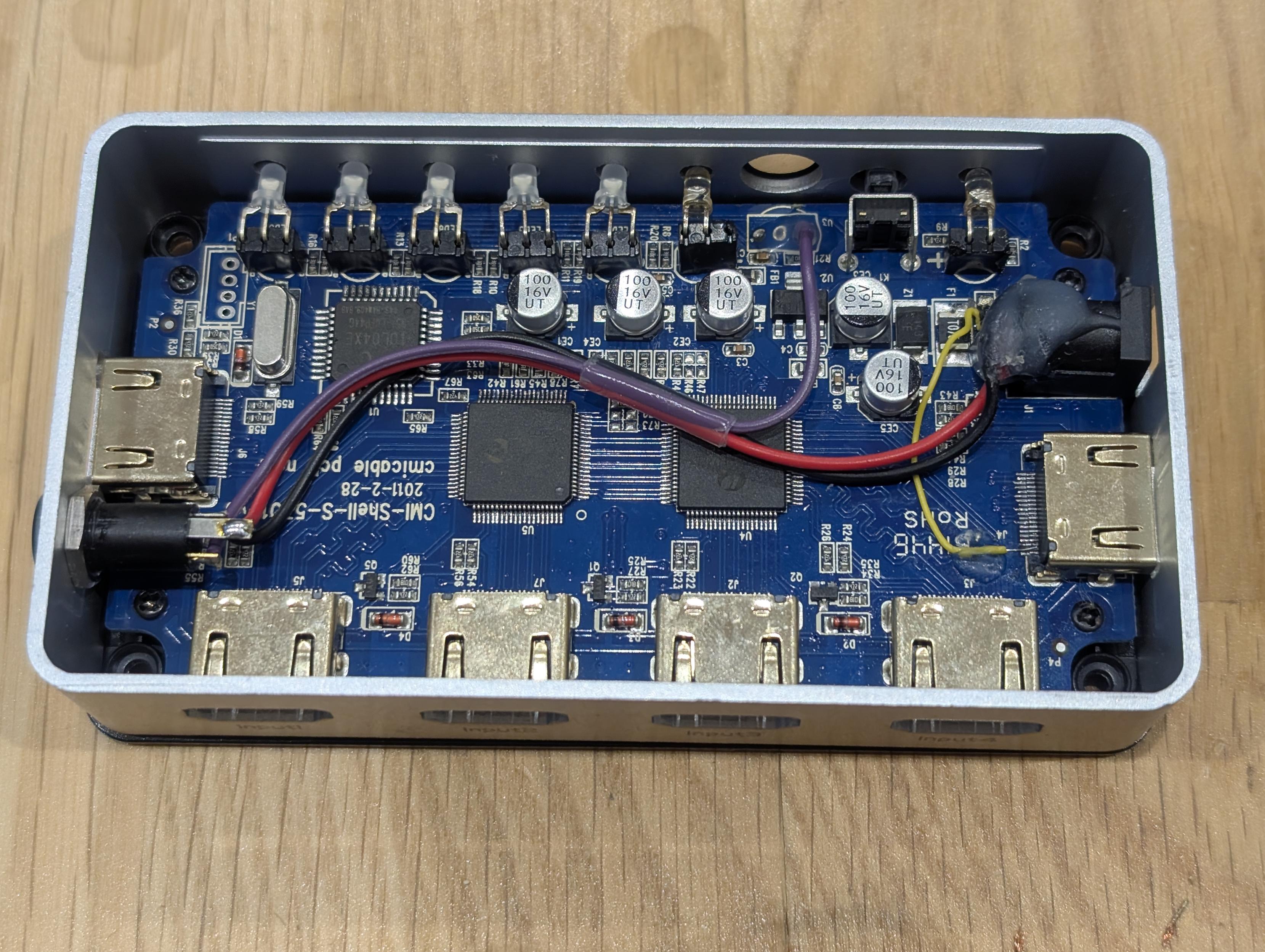
A top-down view of an open HDMI switch resting on a wooden surface, exposing its blue printed circuit board inside a silver metal enclosure. The board features a row of LEDs along the top, four HDMI ports on the bottom edge, and one HDMI port on both the left and right sides. It has clearly been modified: a bundle of red, black, and purple wires runs through a clear heat-shrink tube across the center of the board, connecting the former IR receiver location and original barrel jack to a newly installed 2.5mm TRS jack on the left edge to supply power, ground, and signal. On the right side, a thin yellow bodge wire connects the +5V pin of the side HDMI port to the VCC connection near the main barrel power input, which is secured with hot glue.
https://media.infosec.exchange/infosec.exchange/media_attachments/files/116/709/102/550/276/400/original/9e6c84059be7e3a0.jpg
 Ryan Castellucci (they/them) :nonbinary_flag:
 All GNU social JP content and data are available under the