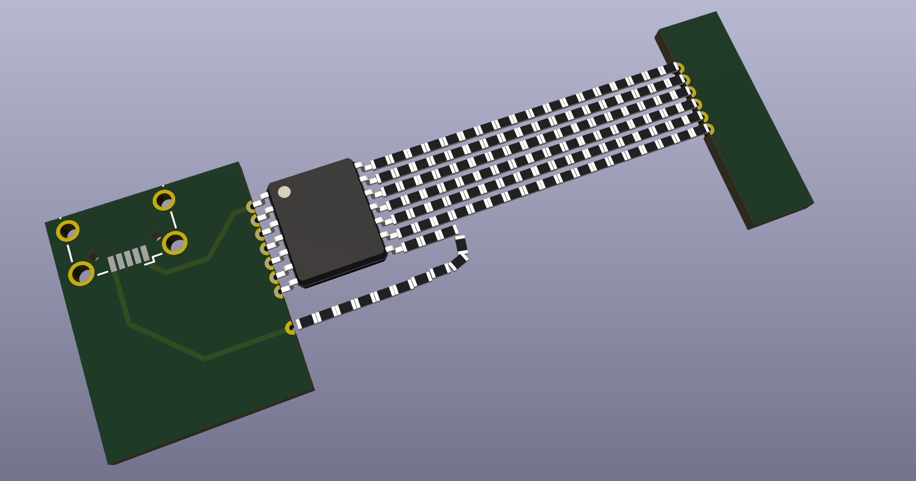
on the left board, I've added a footprint for a USB port, with the top left pin having a trace going to it. the right board has been moved far away, and six of the pins on the chip connected with comically long chains of resistors. the seventh also has a resistor chain coming out of it but it loops back around to the left board and a trace runs up to the usb port. the idea is that they're power and ground but honestly I neither had a specific IC in mind nor looked up which was where on the USB pinout
https://sparkly.uni.horse/system/media_attachments/files/114/061/544/458/990/314/original/204ab1e73eabd128.png