GNU social JP
  • FAQ
  • Login
GNU social JPは日本のGNU socialサーバーです。
Usage/ToS/admin/test/Pleroma FE
  • Public

    • Public
    • Network
    • Groups
    • Featured
    • Popular
    • People

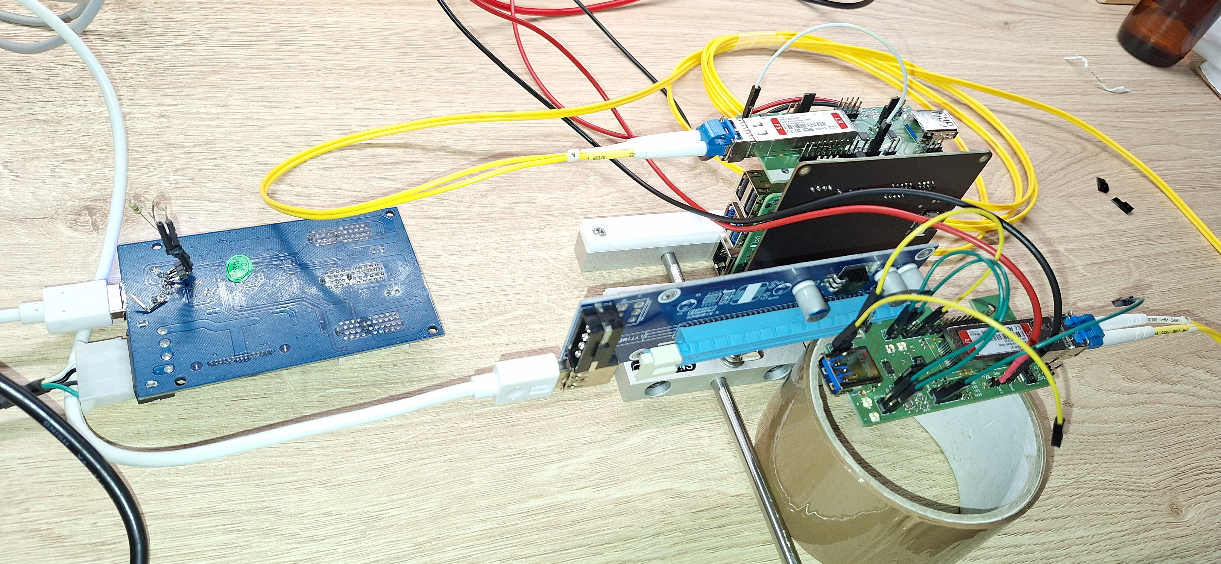
Photo of the setup. On the left side a PCIe switch card with one uplink port going through USB3 cable. It's upside down and 2 resistors are hacked on the PET PCIe lanes to foot RX detection. On the top right, the RPI5 with PCIe hat and my board plugged in it with a SFP module and optical cable coming out. On the bottom right another one of my board with SFP module and optical cable coming in. That one it plugged into a PCIe slot going through USB3 cable, going to the PCIe switch board.

Download link

https://assets.chaos.social/media_attachments/files/113/861/902/480/445/870/original/9dbfd7a8e40b6c29.jpeg

Notices where this attachment appears

  1. Embed this notice
    tnt (tnt@chaos.social)'s status on Tuesday, 21-Jan-2025 16:49:12 JST tnt tnt
    in reply to

    It works 🎉

    Ok, the setup is very janky because of a couple of issue :

    * I of course screwed up TX/RX at one place, so the usb3 connector part didn't work, had to go through the slot to go to the device, ugly but it worked.

    And I swear I had tripled checked ... still screwed up :/

    * The SN75lLVPE802 is meant for SATA not PCIe and doesn't have DC termination. The datasheet say you can use it for PCIe and use 330R to GND to make PCIe RX detect work.

    That doesn't work :/ Had to use lower R.

    In conversation about 4 months ago from gnusocial.jp permalink
  • Help
  • About
  • FAQ
  • TOS
  • Privacy
  • Source
  • Version
  • Contact

GNU social JP is a social network, courtesy of GNU social JP管理人. It runs on GNU social, version 2.0.2-dev, available under the GNU Affero General Public License.

Creative Commons Attribution 3.0 All GNU social JP content and data are available under the Creative Commons Attribution 3.0 license.